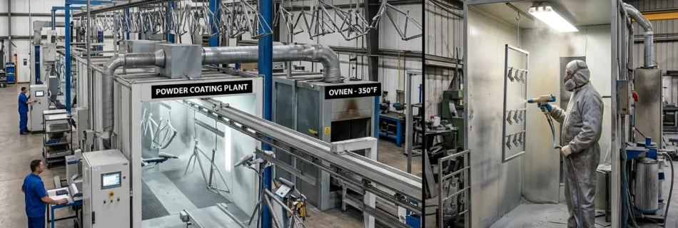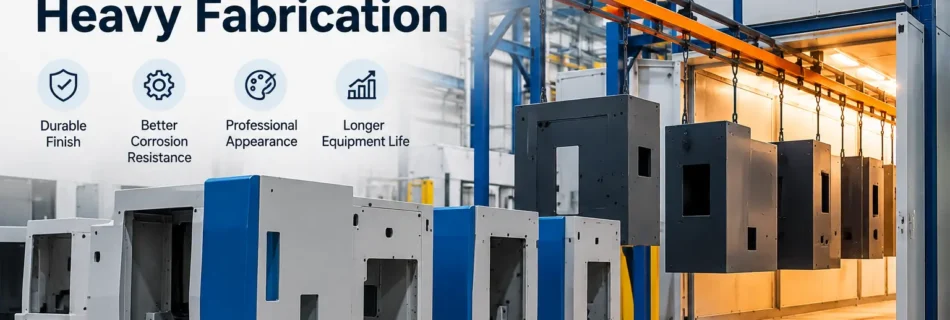
Powder coating plant for CNC machine bodies & heavy fabrication
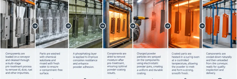
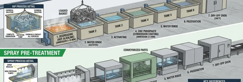
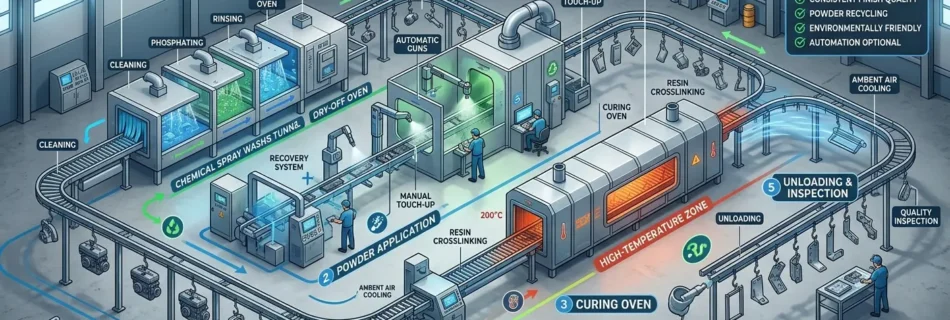
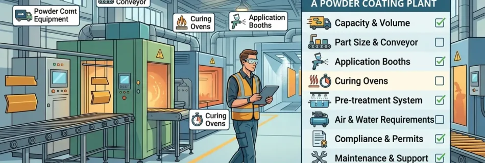
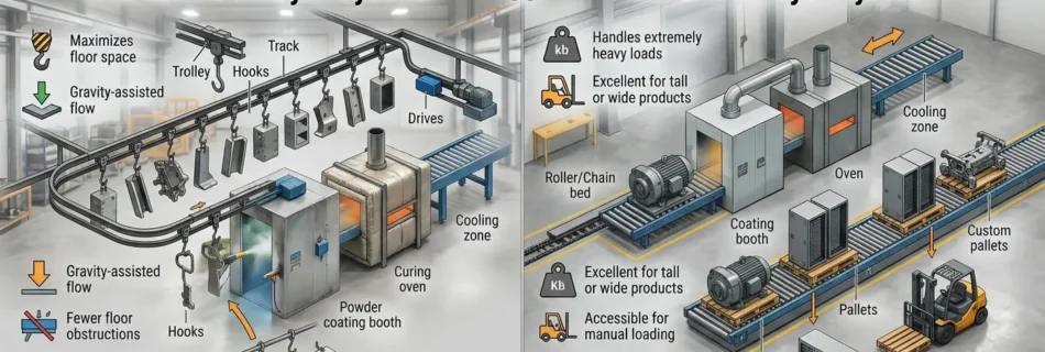
A powder coating plant for CNC machine bodies and heavy fabrication has to solve problems that are much less important in a conventional small-component coating line: high component weight, large dimensions, welded recesses, machining oil, mill scale, precision surfaces that cannot be coated, difficult material handling and the long heat-up time of thick steel. For that reason, the right plant is not simply a larger powder booth and oven. It should be engineered around: maximum part dimensions + maximum part weight + substrate condition + geometry + production volume + surface-preparation requirement + masking requirement + actual thermal mass + curing specification + factory material flow For low-volume or highly varied machine frames, a trolley-loaded batch system may be the most practical solution. For repeat-production CNC enclosures and machine bodies, an overhead conveyor can improve flow. Very heavy weldments may instead require floor conveyors, power-and-free handling or another engineered movement system. Brahma Fabricon’s existing conveyorised powder coating plant range already distinguishes between overhead, power-and-free and floor-conveyor configurations, including floor systems for very heavy fabrication. The important question is not which plant is most automated? It is: Which plant can safely prepare, coat, cure and move your actual machine components at the required production rate? Quick answer Requirement CNC sheet-metal enclosure Heavy welded fabrication Typical construction Sheet metal panels, doors, guards Welded structural steel/frame Primary challenge Finish consistency and recess coverage Weight, scale, contamination and thermal mass Material handling Hanging/conveyor often practical Trolley, floor conveyor or heavy-duty handling may be required Pretreatment Chemical spray/dip commonly considered Blasting and/or chemical treatment may be required depending on surface condition Application Manual, automatic or hybrid Manual or hybrid often useful for complex geometry Masking Threads, hinges, hardware interfaces Machined faces, bores, threads and mounting points Cure challenge Relatively fast heat-up Long part bring-up time Best line type Depends on output Often batch/flexible unless volume justifies automation Main QC concern Film consistency and appearance Cure, adhesion, edge/weld coverage and corrosion protection There is no universal plant layout. A machine-tool OEM producing 100 similar enclosures per shift has a very different requirement from a heavy fabricator coating five large welded frames per day. First, define what “CNC machine body” actually means This distinction is easy to overlook. A CNC machine commonly contains several types of metal components that may all be described informally as the “machine body.” Sheet-metal enclosure This can include: external guards; side panels; front doors; rear panels; electrical cabinet panels; roof covers; splash guards. These parts are generally good candidates for conventional powder coating when the material, pretreatment and service environment are suitable. Welded structural frame The supporting frame may be fabricated from: square or rectangular hollow sections; plate; welded channels; structural members; brackets. These components introduce heavier loading, welded corners, scale, recesses and more thermal mass. Precision machine base or machined structural component A fabricated or cast machine base may contain: machined mounting faces; bearing seats; guideway interfaces; alignment surfaces; bores; tapped holes; datum surfaces. These areas usually require deliberate protection from coating. The plant designer therefore needs drawings showing which areas are coated and which must remain coating-free. What parts of a CNC machine should not be powder coated? Powder should not simply be applied over every visible surface. Depending on the design, areas that may require masking include: precision machined faces; linear-guide mounting surfaces; bearing fits; spindle interfaces; gasket faces; earth/grounding points; threaded holes; dowel holes; electrical contact areas; hydraulic or pneumatic sealing interfaces; identification areas requiring separate treatment. Some components may also contain heat-sensitive assemblies that cannot enter a normal powder-curing cycle. The safest approach is to define coating and masking zones directly on the engineering drawing. Practical procurement insight: send the plant manufacturer both a general component drawing and a marked-up coating boundary drawing. Maximum dimensions alone are not enough to engineer the process. Why CNC bodies and heavy fabrication are difficult to powder coat The basic powder process is straightforward: electrostatically charged powder is attracted to a grounded metal component, then the coating is heated and cured. PCI describes electrostatic spray deposition as the most common powder application process. The difficulty comes from applying that principle consistently to large fabricated structures. Large dimensions The part opening through the: pretreatment equipment; booth; oven; conveyor route; must all accommodate the workpiece plus the fixture and safe operating clearances. High weight A large welded frame may require: reinforced hangers; floor-supported handling; transfer trolleys; lifting equipment; power-and-free conveyors; controlled loading stations. Complex geometry Machine frames contain: box sections; recesses; stiffeners; welded corners; inside angles; deep cavities. Those geometries complicate powder deposition and manual access. Surface contamination Fabrication can introduce: cutting oil; machining coolant; grease; welding residues; rust; scale; fingerprints; shop contamination. PCI notes that cleaning performance matters particularly in powder coating because the process does not contain solvent to compensate for organic soil left on the workpiece. Thermal mass Thick steel needs much longer to heat than a thin enclosure panel. This makes part-metal temperature, rather than the oven display alone, central to curing. Recommended process flow for CNC machine bodies A robust workflow can be structured as: Fabrication complete → inspection → weld/surface correction → degreasing/cleaning → rust/scale removal → conversion treatment where specified → rinsing/drying → masking → loading/grounding → powder application → curing → cooling → de-masking → QC → assembly For heavy weldments requiring abrasive preparation, the sequence may instead incorporate blasting before the final coating preparation steps. The exact preparation route should be defined around the incoming steel condition and required coating performance rather than by copying a generic three-, five- or seven-stage process. Step 1: inspect the fabrication before surface treatment Do not use the coating line to hide fabrication defects. Before pretreatment, inspect for: weld spatter; sharp edges; incomplete welds; grinding marks; excessive rust; mill scale; oil-filled cavities; blocked drain holes; inaccessible recesses; burrs; silicone contamination; permanent labels or hardware installed too early. A coating follows the underlying surface. Poor fabrication preparation can remain visible after cure. Heavy machine frames should therefore reach …
Read more “Powder coating plant for CNC machine bodies & heavy fabrication”