
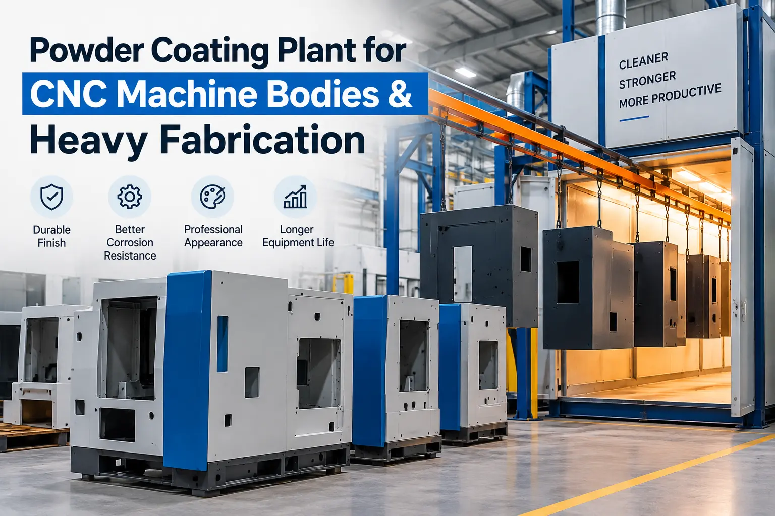
A powder coating plant for CNC machine bodies and heavy fabrication has to solve problems that are much less important in a conventional small-component coating line: high component weight, large dimensions, welded recesses, machining oil, mill scale, precision surfaces that cannot be coated, difficult material handling and the long heat-up time of thick steel.
For that reason, the right plant is not simply a larger powder booth and oven.
It should be engineered around:
maximum part dimensions + maximum part weight + substrate condition + geometry + production volume + surface-preparation requirement + masking requirement + actual thermal mass + curing specification + factory material flow
For low-volume or highly varied machine frames, a trolley-loaded batch system may be the most practical solution. For repeat-production CNC enclosures and machine bodies, an overhead conveyor can improve flow. Very heavy weldments may instead require floor conveyors, power-and-free handling or another engineered movement system.
Brahma Fabricon’s existing conveyorised powder coating plant range already distinguishes between overhead, power-and-free and floor-conveyor configurations, including floor systems for very heavy fabrication.
The important question is not which plant is most automated?
It is:
Which plant can safely prepare, coat, cure and move your actual machine components at the required production rate?
Quick answer
| Requirement | CNC sheet-metal enclosure | Heavy welded fabrication |
|---|---|---|
| Typical construction | Sheet metal panels, doors, guards | Welded structural steel/frame |
| Primary challenge | Finish consistency and recess coverage | Weight, scale, contamination and thermal mass |
| Material handling | Hanging/conveyor often practical | Trolley, floor conveyor or heavy-duty handling may be required |
| Pretreatment | Chemical spray/dip commonly considered | Blasting and/or chemical treatment may be required depending on surface condition |
| Application | Manual, automatic or hybrid | Manual or hybrid often useful for complex geometry |
| Masking | Threads, hinges, hardware interfaces | Machined faces, bores, threads and mounting points |
| Cure challenge | Relatively fast heat-up | Long part bring-up time |
| Best line type | Depends on output | Often batch/flexible unless volume justifies automation |
| Main QC concern | Film consistency and appearance | Cure, adhesion, edge/weld coverage and corrosion protection |
There is no universal plant layout. A machine-tool OEM producing 100 similar enclosures per shift has a very different requirement from a heavy fabricator coating five large welded frames per day.
First, define what “CNC machine body” actually means
This distinction is easy to overlook.
A CNC machine commonly contains several types of metal components that may all be described informally as the “machine body.”
Sheet-metal enclosure
This can include:
- external guards;
- side panels;
- front doors;
- rear panels;
- electrical cabinet panels;
- roof covers;
- splash guards.
These parts are generally good candidates for conventional powder coating when the material, pretreatment and service environment are suitable.
Welded structural frame
The supporting frame may be fabricated from:
- square or rectangular hollow sections;
- plate;
- welded channels;
- structural members;
- brackets.
These components introduce heavier loading, welded corners, scale, recesses and more thermal mass.
Precision machine base or machined structural component
A fabricated or cast machine base may contain:
- machined mounting faces;
- bearing seats;
- guideway interfaces;
- alignment surfaces;
- bores;
- tapped holes;
- datum surfaces.
These areas usually require deliberate protection from coating.
The plant designer therefore needs drawings showing which areas are coated and which must remain coating-free.
What parts of a CNC machine should not be powder coated?
Powder should not simply be applied over every visible surface.
Depending on the design, areas that may require masking include:
- precision machined faces;
- linear-guide mounting surfaces;
- bearing fits;
- spindle interfaces;
- gasket faces;
- earth/grounding points;
- threaded holes;
- dowel holes;
- electrical contact areas;
- hydraulic or pneumatic sealing interfaces;
- identification areas requiring separate treatment.
Some components may also contain heat-sensitive assemblies that cannot enter a normal powder-curing cycle.
The safest approach is to define coating and masking zones directly on the engineering drawing.
Practical procurement insight: send the plant manufacturer both a general component drawing and a marked-up coating boundary drawing. Maximum dimensions alone are not enough to engineer the process.
Why CNC bodies and heavy fabrication are difficult to powder coat
The basic powder process is straightforward: electrostatically charged powder is attracted to a grounded metal component, then the coating is heated and cured. PCI describes electrostatic spray deposition as the most common powder application process.
The difficulty comes from applying that principle consistently to large fabricated structures.
Large dimensions
The part opening through the:
- pretreatment equipment;
- booth;
- oven;
- conveyor route;
must all accommodate the workpiece plus the fixture and safe operating clearances.
High weight
A large welded frame may require:
- reinforced hangers;
- floor-supported handling;
- transfer trolleys;
- lifting equipment;
- power-and-free conveyors;
- controlled loading stations.
Complex geometry
Machine frames contain:
- box sections;
- recesses;
- stiffeners;
- welded corners;
- inside angles;
- deep cavities.
Those geometries complicate powder deposition and manual access.
Surface contamination
Fabrication can introduce:
- cutting oil;
- machining coolant;
- grease;
- welding residues;
- rust;
- scale;
- fingerprints;
- shop contamination.
PCI notes that cleaning performance matters particularly in powder coating because the process does not contain solvent to compensate for organic soil left on the workpiece.
Thermal mass
Thick steel needs much longer to heat than a thin enclosure panel.
This makes part-metal temperature, rather than the oven display alone, central to curing.
Recommended process flow for CNC machine bodies
A robust workflow can be structured as:
Fabrication complete → inspection → weld/surface correction → degreasing/cleaning → rust/scale removal → conversion treatment where specified → rinsing/drying → masking → loading/grounding → powder application → curing → cooling → de-masking → QC → assembly
For heavy weldments requiring abrasive preparation, the sequence may instead incorporate blasting before the final coating preparation steps.
The exact preparation route should be defined around the incoming steel condition and required coating performance rather than by copying a generic three-, five- or seven-stage process.
Step 1: inspect the fabrication before surface treatment
Do not use the coating line to hide fabrication defects.
Before pretreatment, inspect for:
- weld spatter;
- sharp edges;
- incomplete welds;
- grinding marks;
- excessive rust;
- mill scale;
- oil-filled cavities;
- blocked drain holes;
- inaccessible recesses;
- burrs;
- silicone contamination;
- permanent labels or hardware installed too early.
A coating follows the underlying surface. Poor fabrication preparation can remain visible after cure.
Heavy machine frames should therefore reach the finishing department only after the fabrication and dimensional processes that could damage the coating have been completed.
Step 2: choose the surface preparation around the steel condition
Surface preparation is one of the most important decisions in a powder coating plant for heavy fabrication.
AMPP’s surface-preparation guidance covers contamination, surface defects, abrasive blasting, waterjetting, cleanliness and surface profile because coating performance depends substantially on the condition of the substrate before application.
Chemical pretreatment
Chemical cleaning/conversion systems can work particularly well for repeat-production components when:
- parts fit the system;
- contamination is predictable;
- drainage can be controlled;
- chemical stages can reach the required surfaces.
Brahma Fabricon’s powder coating pretreatment technical guide discusses dip, spray and mechanical surface-preparation approaches.
Abrasive blasting
Blasting may become important when fabricated steel has substantial:
- rust;
- mill scale;
- difficult surface contamination;
- existing coating;
- surface-condition requirements calling for mechanical preparation.
AMPP maintains specific standards covering multiple blast-cleaning cleanliness levels rather than treating “sandblasting” as one undefined process.
Combined preparation
Some applications may justify mechanical preparation followed by an appropriate cleaning or chemical treatment process.
The correct route depends on:
- incoming steel condition;
- required corrosion performance;
- powder system;
- customer specification;
- component geometry;
- production economics.
What not to do
Do not assume:
“Heavy fabrication = shot blast only”
or
“Powder coating = seven-tank phosphating.”
Neither is universally correct.
The performance requirement should determine the preparation process.
Step 3: engineer drainage into large fabricated components
Wet pretreatment becomes more complicated when components contain hollow sections and enclosed geometries.
A large machine structure may trap:
- cleaning solution;
- rinse water;
- chemical carryover;
- moisture.
That can create problems later during drying or curing.
Part design and hanging orientation should therefore be reviewed for:
- drain holes;
- closed cavities;
- horizontal pockets;
- overlapping sheet construction;
- inaccessible channels.
This is one reason coating-engineering input is valuable before fabrication drawings are frozen, rather than only after the machine frame has been manufactured.
Step 4: protect machined faces and precision interfaces
Masking is particularly important for CNC machine manufacturing.
Depending on the component, masking may be required at two different points:
During mechanical preparation
Precision faces may require protection from abrasive blasting or aggressive surface treatment.
During powder application and curing
High-temperature plugs, caps, tapes or custom masks can be used where coating must not enter.
Typical areas include:
- threaded holes;
- precision bores;
- linear rail mounting faces;
- dowel locations;
- grounding studs;
- bearing seats;
- mating flanges.
The masking material itself must be compatible with the process temperature and chemistry.
Design insight
If the same product is manufactured repeatedly, custom reusable masks can reduce operator variation and masking time compared with improvising protection for every component.
Step 5: select material handling before selecting the booth
For heavy fabrication, material handling should not be an afterthought.
The movement system determines how the component reaches:
- pretreatment;
- drying;
- powder application;
- curing;
- cooling;
- inspection.
Common options include:
Trolley-loaded batch system
Often suitable for:
- very large frames;
- lower production volumes;
- mixed dimensions;
- job-shop work;
- irregular product families.
Overhead conveyor
Useful where components can be safely suspended and there is sufficient repeat volume.
Brahma Fabricon’s conveyorised range identifies overhead systems as a common solution for machine bodies and medium-to-heavy components.
Power-and-free conveyor
Power-and-free designs allow workpieces to accumulate or move through different process segments independently. PCI defines a power-and-free conveyor as a two-track arrangement that enables products to move at different speeds and through different routes.
That can be valuable where heavy product families need different:
- dwell times;
- buffering;
- loading cycles;
- process routes.
Floor conveyor
A floor-supported system becomes worth evaluating when the component mass makes overhead handling impractical.
Brahma Fabricon’s current conveyorised plant page specifically positions floor conveyor systems for very heavy fabrication.
Step 6: make grounding part of fixture design
A heavy workpiece may look like an excellent electrical conductor, but poor fixture contact can still interfere with electrostatic powder application.
PCI identifies dirty hangers and poor conveyor grounding as common causes of powder failing to deposit properly. Its technical guidance states that coating buildup at hanger or conveyor contact points can degrade the electrical path to ground.
For CNC frames, this makes the rack or trolley a process tool rather than simply transport equipment.
Specify:
- deliberate bare-metal contact points;
- repeatable fixture locations;
- easy-to-clean contacts;
- grounding checks;
- hanger maintenance.
Where possible, locate the electrical contact on a surface that will later be concealed or intentionally left uncoated.
Step 7: choose a booth that operators can actually coat inside
A booth for CNC bodies must be sized for operator access and airflow, not merely for part clearance.
Large industrial parts can require:
- walk-in access;
- opposing manual spray stations;
- automatic guns plus touch-up positions;
- enhanced lighting;
- sufficient extraction across a large opening;
- safe access around the frame.
Nordson’s current powder booth portfolio includes special-application XXL systems for large or heavy components used in industrial fabrication, while its manual booth range specifically accommodates applications from individual pieces to large products.
Booth sizing questions
Before approving the booth, ask:
- Can the largest part physically enter?
- Is there clearance around the fixture?
- Can an operator reach internal faces safely?
- Are deep recesses visible?
- Can the extraction system contain overspray with the required opening?
- Where will manual touch-up occur?
- How will the booth be cleaned?
- Is reclaim worthwhile for the production mix?
Manual, automatic or hybrid application?
For CNC machine bodies and heavy fabricated frames, hybrid coating often deserves serious consideration.
Manual application
Useful when:
- product geometry varies frequently;
- volume is modest;
- internal corners require judgement;
- many one-off parts are coated.
Automatic application
More attractive when:
- part families are repeatable;
- hanger position is controlled;
- production volume is high enough;
- external surfaces dominate.
Automatic + manual touch-up
This combines automatic coverage of repeatable open surfaces with operator attention to:
- recesses;
- weld zones;
- internal corners;
- cavities;
- Faraday-cage areas.
PCI identifies electrostatics, airflow, booth design and grounding as important variables affecting powder transfer efficiency, reinforcing why simply adding more automatic guns is not a complete solution.
Why deep corners are difficult to coat
CNC enclosures and welded frames contain many electrically shielded corners.
Charged powder preferentially moves toward easier-to-reach grounded surfaces. Recesses may therefore receive less powder unless:
- gun position;
- voltage/current;
- airflow;
- nozzle;
- part orientation;
- manual reinforcement
are optimized.
PCI specifically notes that good grounding affects transfer efficiency and Faraday-cage penetration.
This is another reason why the plant should be tested using actual representative CNC components, not flat sample panels alone.
Step 8: size the curing oven for thermal mass
This is one of the most important differences between sheet-metal coating and heavy fabrication.
Powder does not cure merely because the oven air reaches a set temperature.
The workpiece itself must achieve the cure schedule specified for the powder.
PCI defines part bring-up time as the time required to heat a component to its desired metal temperature and explains that dwell time refers to holding the substrate at cure temperature according to the coating’s cure schedule.
For heavy steel:
Total oven residence = part heat-up time + required cure dwell
A thick welded frame can therefore require a completely different oven calculation from a 1.5 mm enclosure panel.
Why the largest part is not enough to size the oven
Suppose two components have identical outside dimensions.
Component A: sheet-metal enclosure.
Component B: heavy welded base.
They can fit inside the same oven, yet their thermal behavior will be very different.
The supplier should therefore calculate oven requirements using:
- component mass;
- steel thickness;
- surface area;
- load density;
- starting temperature;
- powder cure schedule;
- heating method;
- airflow;
- production rate.
Brahma Fabricon’s powder curing oven range includes batch and conveyorised configurations for heavy fabrication, but the final selection still needs to be based on the actual thermal load.
Verify part-metal temperature
For repeat production, consider using an oven profiler or thermocouples to verify what the component experiences throughout the curing cycle.
This can answer questions such as:
- When does the thickest section reach cure temperature?
- Does one side heat faster?
- Is the component receiving sufficient dwell?
- Are thin panels being exposed unnecessarily while a heavy frame reaches temperature?
- Can conveyor speed be increased safely?
Heavy-fabrication curing should be validated using actual production loads.
Do not rely only on the oven-controller display.
Batch vs conveyorised plant for CNC and heavy fabrication
| Factor | Batch plant | Conveyorised plant |
|---|---|---|
| Product variation | Excellent | Best with repeatable product families |
| Very heavy components | Often practical | Requires engineered handling |
| Low production volume | Strong fit | May be underutilized |
| High production volume | Can become labour-intensive | Strong fit |
| Large product changes | Flexible | More layout-dependent |
| Cure time variation | Easy to adapt by batch | Must be coordinated with line movement |
| Capital investment | Generally lower | Generally higher |
| Automation potential | Moderate | High |
| Material handling | Trolley/crane/manual | Integrated |
| Factory footprint | Can be compact but needs staging | Requires engineered line route |
| Best use | Heavy/high-mix/low-volume | Repeat medium/high-volume |
Do not choose based only on annual volume
Two OEMs producing the same number of machines per year may still require different plants.
One may manufacture identical CNC enclosures.
The other may build custom machines where every frame is different.
Product repeatability matters almost as much as total volume.
Which conveyor is best for heavy machine bodies?
There is no universal answer.
Overhead conveyor
Consider when:
- the component can be safely hung;
- fixture load is manageable;
- repeat production justifies continuous handling.
Power-and-free
Consider when:
- multiple part families share one plant;
- accumulation is needed;
- stations have different process times;
- buffering improves production flow.
Floor conveyor
Consider when:
- the component is very heavy;
- suspending it is difficult;
- low-level loading improves handling;
- plant layout permits floor movement.
Batch trolley
Consider when:
- daily volume is modest;
- frame dimensions vary;
- flexibility matters more than continuous throughput.
The equipment quotation should explain why the proposed handling architecture matches the product mix.
Powder selection for CNC machine bodies
Do not select powder solely by colour or gloss.
Machine-tool coatings can be exposed to:
- cutting fluids;
- lubricating oils;
- cleaners;
- operator contact;
- impact;
- abrasion;
- humidity;
- occasional chemicals;
- UV exposure if equipment operates outdoors.
The coating chemistry should therefore be selected against the actual service environment and verified using the powder manufacturer’s technical documentation.
Broadly:
Epoxy systems are often associated with strong chemical performance but typically are not selected where exterior UV retention is important.
Polyester systems are commonly used where weatherability is required.
Hybrid systems can be useful for certain indoor applications.
The exact formulation-and not only the generic resin family-determines performance.
For a CNC manufacturer, testing the proposed finish against the actual coolant and cleaning chemicals used by customers can be more useful than choosing a powder based solely on a generic hardness claim.
Special consideration: cast components and outgassing
If a machine assembly includes porous castings or certain other substrates, heating can release trapped gas.
PCI defines outgassing as subsurface gas escaping during coating and notes that it can create bubbles, blisters or pinholes.
If cast parts are to be powder coated, the coating supplier and plant engineer may need to consider:
- preheating;
- degassing;
- substrate condition;
- powder designed for outgassing tolerance;
- cure profile.
Do not assume the process developed for fabricated sheet steel can automatically be transferred to cast machine components.
Typical plant configuration for CNC machine enclosures
For repeat sheet-metal enclosures, a line might include:
Loading → spray/dip pretreatment → dry-off → automatic/manual powder booth → recovery → conveyorised cure oven → cooling → QC → unloading
Automation can be attractive because enclosure geometry and hanging position are often repeatable.
Typical plant configuration for heavy welded frames
For heavy, low-to-medium-volume frames, a more flexible layout may be:
Fabrication inspection → blasting/cleaning as specified → chemical preparation if required → drying → masking → trolley loading → walk-in/manual powder booth → batch curing oven → controlled cooling → QC
If production volume justifies continuous movement, the material-handling system can then be upgraded toward power-and-free or floor-conveyor architecture.
The best configuration should follow production economics rather than the assumption that a conveyorised line is always superior.
Equipment selection checklist
| Equipment | Critical CNC/heavy-fabrication question |
|---|---|
| Pretreatment | Can the largest frame be cleaned uniformly? |
| Blast system | Can scale/rust be removed without damaging precision surfaces? |
| Dry-off oven | Can trapped water be removed from hollow sections? |
| Booth | Can operators reach recessed and internal areas? |
| Spray guns | Can settings be controlled for flat faces and deep recesses? |
| Recovery | Is reclaim economical for the actual colour mix? |
| Fixtures | Can the part be held safely with reliable grounding? |
| Conveyor | Is maximum hanger/trolley load based on real parts? |
| Cure oven | Is sizing based on thermal mass, not only dimensions? |
| Controls | Can recipes be stored for different machine families? |
| QC equipment | Can film build and cure be verified? |
| Lifting | How will heavy parts be transferred safely? |
How to calculate plant capacity
For CNC machine manufacturing, plant capacity should be expressed as acceptable machine components per shift, not simply conveyor speed.
For a conveyorised line:
Parts per hour = conveyor travel per hour ÷ hanger pitch × parts per hanger
But that is only theoretical capacity.
Real production must also account for:
- loading time;
- unloading;
- pretreatment dwell;
- powder application;
- manual reinforcement;
- cure requirement;
- colour change;
- maintenance;
- rejects.
For large frames, ask the supplier to show a cycle-time balance across the whole finishing process.
If the booth can process 12 frames per hour but the oven can cure only 7 at the required thermal profile, the plant capacity is not 12.
Important information to send with an RFQ
A strong quotation request should include:
Component data
- minimum dimensions;
- typical dimensions;
- maximum dimensions;
- maximum weight;
- fabrication material;
- steel thickness;
- photographs;
- 2D/3D drawings.
Production data
- parts per shift;
- shifts per day;
- product families;
- batch size;
- current production;
- projected production.
Coating specification
- powder chemistry if predetermined;
- film-thickness requirement;
- finish;
- RAL colour;
- gloss;
- corrosion requirement;
- chemical-resistance requirement;
- customer/OEM standard.
Process constraints
- areas requiring masking;
- machined faces;
- hollow sections;
- coolant exposure;
- colour-change frequency.
Factory information
- available floor area;
- clear height;
- crane coverage;
- loading doors;
- electrical supply;
- LPG/PNG availability;
- compressed air;
- water;
- drainage.
A site-layout drawing is much more useful than simply asking:
“Send price for a heavy-duty powder coating plant.”
Common coating problems on CNC bodies and heavy fabrication
| Problem | Areas to investigate first |
|---|---|
| Poor adhesion | Cleaning, oil contamination, scale, pretreatment, cure |
| Pinholes | Trapped contamination, moisture, outgassing |
| Thin powder in recesses | Faraday effect, grounding, gun settings, access |
| Uneven film build | Gun distance, manual technique, geometry, grounding |
| Rust around welds | Weld preparation, pretreatment, edge coverage |
| Powder on machined face | Masking design/process control |
| Thread contamination | Plugging/masking |
| Under-cure | Part-metal temperature and dwell |
| Oven marks/handling damage | Fixtures and component support |
| Colour contamination | Booth cleaning and powder-management practices |
| Water marks | Pretreatment rinsing, drainage or dry-off |
The most efficient troubleshooting method is to identify which process stage created the defect, rather than immediately changing the gun settings.
Quality control for CNC machine bodies
Finished machine panels may look satisfactory while still failing a technical specification.
A suitable QC plan can include:
Film thickness
ISO 2808:2019 describes methods for measuring coating film thickness and remains current after confirmation in 2026.
Film readings should be taken across representative:
- flat panels;
- corners;
- recessed sections;
- welded areas;
rather than at one convenient point.
Cross-cut resistance
ISO 2409:2020 specifies the cross-cut procedure for evaluating resistance to coating separation. Importantly, ISO explicitly notes that the method is not itself a direct measurement of adhesion.
That nuance is worth preserving in the quality plan.
Cure verification
For thick components, profile:
- part temperature;
- heat-up time;
- dwell;
- oven variation.
Appearance
Inspect:
- gloss;
- texture;
- colour consistency;
- contamination;
- pinholes;
- orange peel;
- coverage.
Masking accuracy
Verify that precision surfaces, threaded features and ground points remain within drawing requirements.
How plant design affects cost
The investment cannot be estimated responsibly from part dimensions alone.
Major cost drivers include:
- pretreatment complexity;
- blast preparation;
- maximum workpiece size;
- maximum load;
- booth volume;
- recovery technology;
- number of spray stations;
- automatic guns;
- reciprocators;
- oven dimensions;
- thermal load;
- conveyor type;
- lifting/transfer equipment;
- controls;
- factory modifications;
- exhaust and utilities.
The correct economic metric is:
Total finishing cost per acceptable CNC machine or fabricated component
rather than the purchase price of the coating plant.
A flexible batch line can sometimes generate a better return than a large automatic line when production volume is low or component variety is high.
Where automation provides the most value
Automation should solve a measurable manufacturing problem.
| Problem | Potential automation |
|---|---|
| Repetitive external panels | Automatic guns |
| Inconsistent gun movement | Reciprocator |
| Multiple CNC models | Recipe control |
| Variable loading | Power-and-free buffering |
| Unstable conveyor speed | VFD-controlled movement |
| Cure variation | Temperature monitoring/profile validation |
| Large colour volume | Powder recovery/management |
| Labour-intensive movement | Engineered conveyor/transfer system |
| Frequent operator settings | PLC/HMI recipe storage |
A useful design question is:
Which variable are we trying to remove from the process?
If automation does not improve consistency, safety, throughput or cost, it may not justify the investment.
When powder coating may not be the best option
Powder coating is widely used on industrial machinery and can provide a tough protective and decorative finish. PCI specifically cites machinery among the demanding applications for powder coatings.
However, it is not automatically the correct finishing method for every machine component.
Evaluate alternatives when:
- the assembled unit contains heat-sensitive electronics;
- seals or lubricants cannot tolerate the cure cycle;
- the structure is too large for practical oven curing;
- coating must be repaired frequently in the field;
- precision areas are extremely difficult to mask;
- only one or two oversized fabrications are produced occasionally;
- the required finish specification favors another coating technology.
For some very large structures, industrial liquid coating may be operationally more practical because it does not require heating the complete component inside a curing oven.
A good equipment supplier should be willing to say when powder coating is not the optimal process.
Common mistakes when buying a plant for heavy fabrication
Designing from part size but ignoring weight
A component may fit through the booth but exceed the safe handling-system capacity.
Sizing the oven from dimensions only
Thermal mass can be more important than external dimensions.
Coating over poor fabrication preparation
Powder does not remove weld spatter, scale or sharp-edge problems.
Forgetting machined surfaces
Masking requirements can significantly affect process time and fixture design.
Selecting an overhead conveyor automatically
Some workpieces are better suited to trolley or floor-supported movement.
Automating complex frames too early
Variable geometry can make manual or hybrid application more economical.
Ignoring crane and forklift routes
The coating line must fit into the factory’s actual material flow.
Accepting generic cure times
Use the powder supplier’s cure specification and validate it at the component.
Ignoring future product families
A plant designed tightly around today’s machine may become restrictive when a larger model is introduced.
What should a supplier calculate before giving you a final proposal?
Before issuing the final technical offer, the plant supplier should be able to explain:
- Maximum allowable component dimensions and load.
- How the proposed handling system carries that load.
- Pretreatment sequence and why it suits the substrate.
- Booth opening and operator-access requirement.
- Manual vs automatic gun strategy.
- Proposed powder-recovery approach.
- Oven heat-load assumptions.
- Part heat-up and cure methodology.
- Required production cycle time.
- Connected electrical load.
- Fuel requirement where applicable.
- Compressed-air demand.
- Water and pretreatment requirements.
- Floor-space requirement.
- Loading and unloading arrangement.
- QC and temperature-profile methodology.
- FAT/SAT acceptance criteria.
- Recommended critical spare parts.
If these points are missing, two apparently similar quotations may actually describe very different systems.
Practical plant-selection framework
Use this order:
1. Categorize the parts.
Separate sheet-metal enclosures, welded frames and heavy precision structures.
2. Record maximum size and weight.
Include the fixture.
3. Define the surface condition.
Oil, rust, mill scale and weld condition matter.
4. Define protected surfaces.
Mark machining and masking zones.
5. Define coating performance.
Corrosion, appearance, chemical resistance and environment.
6. Calculate throughput.
Use actual components per shift.
7. Select pretreatment.
Chemical, mechanical or combined.
8. Select handling.
Batch trolley, overhead, floor or power-and-free.
9. Select application strategy.
Manual, automatic or hybrid.
10. Calculate curing from thermal mass.
Do not size from chamber temperature alone.
11. Map the line into the factory.
Include cranes, forklifts and maintenance access.
12. Define acceptance criteria before ordering.
This sequence produces a substantially better specification than starting by asking for a standard plant catalogue.
Why a custom plant is usually necessary for heavy fabrication
A standard powder coating system assumes a fairly predictable work envelope.
Heavy engineering rarely provides one.
Variation in:
- component dimensions;
- lifting method;
- frame geometry;
- thermal mass;
- masking;
- pretreatment;
- throughput;
means that the material-handling, booth and oven normally need to be evaluated together.
Brahma Fabricon’s website lists CNC machine bodies and heavy industrial components among the applications shown in its project portfolio and offers batch, overhead, power-and-free and floor-conveyor configurations.
Manufacturers planning such a line can first review the company’s complete powder coating plant range and powder coating equipment options, then provide actual component drawings for a project-specific layout.
FAQ
Can CNC machine bodies be powder coated?
Yes. Fabricated steel enclosures, guards, panels and many machine frames can be powder coated when the substrate is prepared properly and the component can tolerate the required curing cycle. Precision-machined and electrical-contact surfaces generally need to be masked or otherwise protected.
Which powder coating plant is best for CNC machine bodies?
It depends on part size, weight, production volume and variation. Repetitive sheet-metal machine enclosures may suit a conveyorised line, while large, heavy or highly variable frames may be better suited to a trolley-loaded batch plant or engineered floor/power-and-free system.
Can heavy fabricated steel frames be powder coated?
Yes, provided the plant can safely prepare, handle, spray and cure the complete workpiece. Particular attention should be given to mill scale, weld condition, part weight, grounding, access to recesses and the longer heat-up time of heavy steel.
How are machined surfaces protected during powder coating?
Machined faces, threaded holes, bores and precision interfaces can be protected using suitable masking tapes, plugs, caps, fixtures or reusable masks. Some surfaces may also require protection during abrasive surface preparation.
Is shot blasting required before powder coating heavy fabrication?
Not always. Abrasive blasting is useful where rust, mill scale or surface-condition requirements justify mechanical preparation, but the correct cleaning and pretreatment sequence should be selected from the incoming substrate condition and required coating performance. AMPP maintains separate standards for different surface-preparation methods and cleanliness levels.
Why do heavy machine frames require longer curing cycles?
A heavy steel frame usually takes longer than thin sheet metal to reach the required part-metal temperature. The cure cycle must therefore account for both the component’s heat-up period and the coating manufacturer’s required dwell at cure temperature.
Is a batch or conveyorised plant better for heavy fabrication?
Batch plants generally offer greater flexibility for very large, variable or lower-volume components. Conveyorised systems become more attractive when part families, loading and production volumes are sufficiently repeatable.
What conveyor is suitable for very heavy machine frames?
Depending on workpiece weight and factory layout, options include heavy-duty overhead systems, power-and-free conveyors, floor conveyors or trolley-based handling. A structural and mechanical assessment of the actual maximum load is required before selection.
What quality tests should be performed after coating?
The quality plan can include visual inspection, coating-thickness measurement, cure verification, masking inspection and application-specific coating tests. ISO 2808:2019 covers film-thickness measurement, while ISO 2409:2020 defines the cross-cut test.
What information is required for a powder coating plant quotation?
Provide maximum and typical part dimensions, weight, drawings, substrate, production per shift, required coating specification, colour-change frequency, masking details, factory layout and available utilities. For heavy components, include lifting and material-handling information as well.
Conclusion
A powder coating plant for CNC machine bodies and heavy fabrication should be engineered around the workpiece-not selected from a standard plant size.
The most important decisions are:
surface preparation → masking → material handling → grounding → booth access → application method → actual part curing → inspection
For CNC manufacturers, it is particularly important to distinguish lightweight enclosures from welded frames and precision machine structures. They may share a colour and final appearance, but their coating-process requirements can be completely different.
For heavy fabricators, the three parameters that deserve early attention are maximum component weight, surface condition and thermal mass. These frequently determine whether a conventional overhead conveyor is practical, whether blasting is needed, and how large the curing system really needs to be.
Brahma Fabricon manufactures powder coating systems from Vadodara and lists CNC machine bodies and heavy fabrication among its application areas. Manufacturers planning a new line can review its powder coating plant systems, pretreatment solutions and powder curing ovens, then submit maximum part dimensions, weight, drawings and required production through the project enquiry page.