
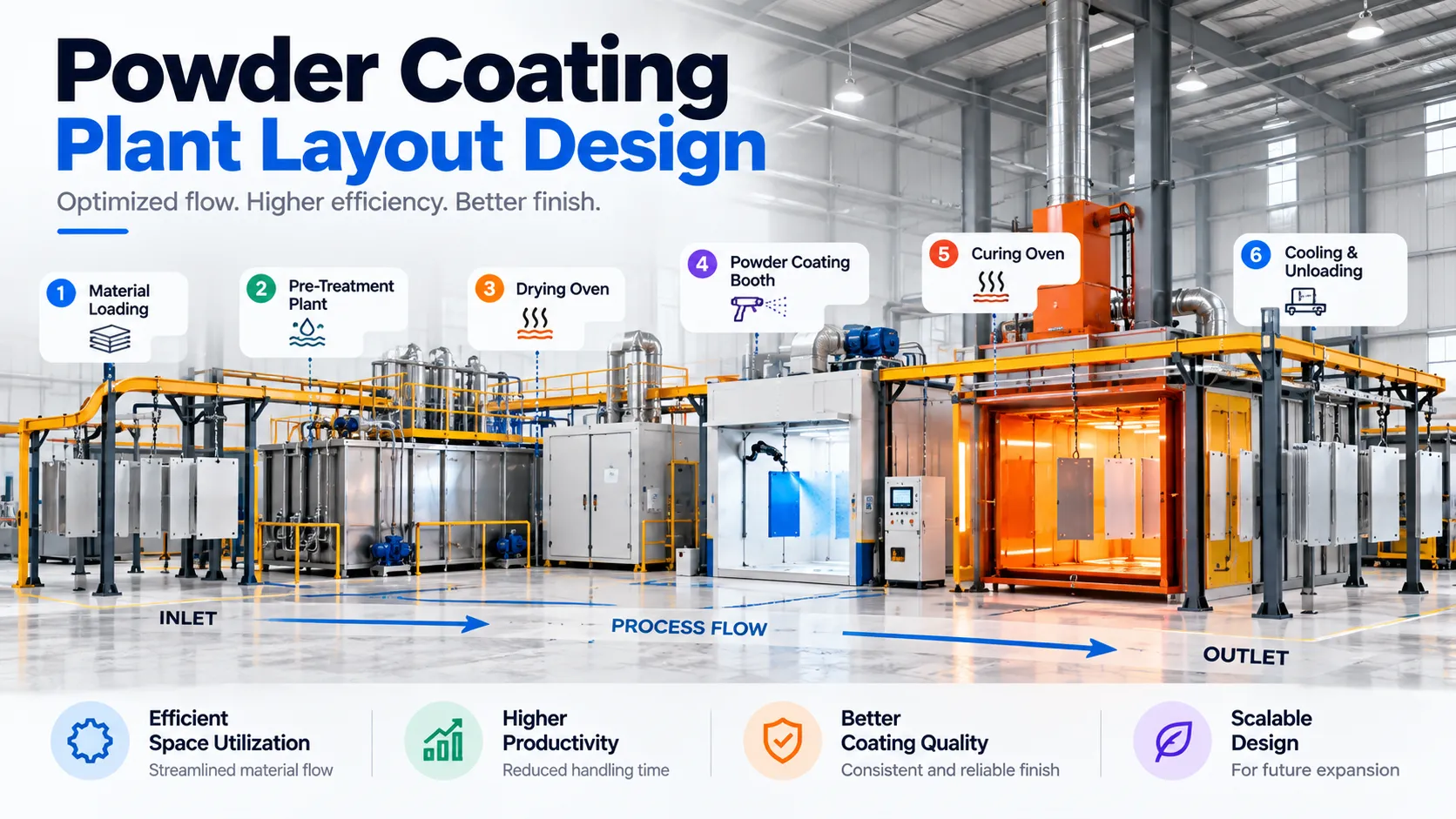
A good powder coating plant layout is not simply a drawing showing where the pretreatment system, booth and oven will fit.
It is the physical design of the complete production flow:
incoming component → loading → pretreatment → drying → powder application → curing → cooling → inspection → unloading or assembly
The layout must also accommodate conveyor movement, operator access, maintenance, utilities, powder and chemical storage, wastewater handling, forklifts or cranes, work-in-progress and future expansion.
That is why the correct starting question is not:
“How many square feet does a powder coating plant need?”
It is:
“What products must move through the plant, at what rate, through which processes, and within what building constraints?”
Current engineering guidance from multiple coating-line specialists follows the same principle: define the part, output and building first, then design the equipment and line around them.
Manufacturers planning a complete system can use Brahma Fabricon’s powder coating plant solutions as the supporting commercial page while using this guide to plan the factory layout before final equipment selection.
Quick Summary: What Should a Powder Coating Plant Layout Include?
A complete layout should account for:
| Area | Main planning requirement |
|---|---|
| Incoming/WIP area | Space for uncoated components waiting for finishing |
| Loading station | Safe and ergonomic hanging/loading |
| Pretreatment | Process length, tanks/tunnel, drainage and chemical access |
| Dry-off | Correct position after wet pretreatment |
| Powder booth | Clean environment, operator access and recovery equipment |
| Curing oven | Residence time, conveyor route and heat isolation |
| Cooling | Enough distance/time before handling |
| Inspection | Accessible QC area with adequate lighting |
| Unloading | Safe removal from conveyor or trolley |
| Finished-goods staging | Separation from dirty incoming components |
| Powder storage | Controlled storage near application area without obstructing booth service |
| Chemical storage | Safe access near pretreatment without contaminating clean zones |
| Utilities | Power, fuel, air, water, exhaust and drainage |
| Maintenance | Access around fans, filters, burners, pumps and conveyor drives |
| ETP/wastewater | Appropriate location relative to pretreatment drainage |
| Expansion space | Provision for future capacity or additional equipment |
The actual plant footprint is the result of all of these zones—not simply the dimensions printed on equipment drawings.
What Is a Powder Coating Plant Layout?
A powder coating plant layout is the planned physical arrangement of pretreatment, drying, powder application, curing, material handling, utilities, inspection and support areas inside a manufacturing facility.
A good layout aims to move components through the finishing process with minimal unnecessary movement while preserving:
- production capacity;
- coating quality;
- safe operation;
- maintenance access;
- utility access;
- operator ergonomics;
- future scalability.
The conveyor is often the structural backbone of an automatic line because its route connects every major process stage.
For a deeper understanding of the individual stages before planning their placement, see Brahma Fabricon’s powder coating process guide.
Start With the Product, Not the Building Drawing
Factory dimensions matter, but product information should come first.
Before a layout is developed, document the workpieces that will use the line.
Maximum part envelope
Record:
- maximum length;
- maximum width;
- maximum height;
- maximum weight.
For conveyorised plants, calculate these dimensions in the actual hanging orientation, including the fixture.
A 1,500 mm-high product may require substantially more vertical clearance once a hanger, trolley, conveyor track and safety clearance are added.
Typical part envelope
The largest product determines whether equipment can physically accommodate the workpiece.
The typical product, however, often determines:
- production economics;
- hanger density;
- booth utilization;
- energy use;
- conveyor loading.
Do not optimize the entire line around a rare oversized component if 90% of production is much smaller without first testing the economic consequences.
Product geometry
Document:
- flat faces;
- cavities;
- recesses;
- hollow sections;
- water traps;
- masking requirements;
- hanging points.
Geometry affects pretreatment drainage, booth access and fixture orientation.
Production requirement
Define:
- parts/hour;
- parts/shift;
- shifts/day;
- days/month;
- expected future production.
Sundial’s current layout guidance similarly identifies workpiece dimensions, weight, substrate, geometry and throughput as fundamental inputs before determining line equipment.
Factory Space: Total Area Is Not the Same as Usable Area
One of the biggest powder coating plant layout mistakes is looking only at factory floor area.
A building may have enough total square metres while still being unsuitable for the intended line.
Usable space is reduced by:
- structural columns;
- walls;
- fire exits;
- electrical rooms;
- existing machines;
- staircases;
- crane columns;
- forklift lanes;
- storage zones;
- operator walkways;
- maintenance clearances;
- utility equipment.
Recent coating-line layout guidance specifically warns that equipment fitting into a CAD plan does not mean the production line is operationally workable; columns, doors, maintenance space and material routes need to be evaluated together.
Use this distinction
Gross factory space
= total available floor area.
Usable equipment space
= gross area minus structural, safety and operational restrictions.
Required process space
= equipment footprint + conveyor route + service clearance + operating clearance + staging + utilities.
The project is viable only when required process space fits inside usable space.
Ceiling Height Can Be More Restrictive Than Floor Area
A coating plant is three-dimensional.
For an overhead conveyor system, required building height may need to accommodate:
floor clearance + hanging component + fixture + conveyor trolley/track + structural supports + service clearance
This becomes particularly important for:
- tall control panels;
- machinery frames;
- long vertically hung components;
- large cabinets;
- agricultural machinery;
- heavy fabrications.
Elektrosprey identifies ceiling height as a frequently overlooked constraint because a plant can sometimes be extended horizontally, whereas raising an existing roof is much more difficult.
Before designing the conveyor route, provide the supplier with:
- clear internal height;
- beam height;
- crane level;
- ductwork;
- sprinkler/service locations;
- roof obstructions.
The Basic Powder Coating Plant Process Layout
For many conveyorised systems, the conceptual sequence is:
Incoming Parts
      ↓
Loading
      ↓
Pretreatment
      ↓
Dry-Off Oven
      ↓
Cooling / Stabilization
      ↓
Powder Coating Booth
      ↓
Curing Oven
      ↓
Cooling
      ↓
Inspection
      ↓
Unloading
      ↓
Finished Parts / Assembly

The diagrams above are useful conceptual references, but the final Brahma Fabricon article should use an original branded plant-layout diagram based on its own engineering approach rather than reproducing competitor artwork.
Four Common Powder Coating Plant Layout Types
There is no single ideal geometry.
The building, part flow and conveyor configuration determine the best arrangement.
1. Linear layout
A linear plant follows a relatively straight sequence:
Load → pretreatment → dry-off → booth → oven → cool → unload
Advantages
- easy process visualization;
- simple material flow;
- reduced crossover;
- straightforward conveyor routing.
Limitations
- requires a long factory bay;
- loading and unloading may be far apart;
- can require longer operator/forklift travel.
Best suited for
Long buildings with clear end-to-end material flow.
2. U-shaped layout
The process folds back toward its starting side.
Advantages
- load and unload can be positioned closer together;
- potentially shorter operator movement;
- compact use of certain factory shapes;
- one supervision area can observe more of the line.
Limitations
- additional conveyor turns;
- careful spacing needed between process equipment;
- return path must not create contamination or heat problems.
Best suited for
Wide buildings where there is insufficient straight-line length.
3. L-shaped layout
An L-layout changes direction once around factory constraints.
Advantages
- works around columns or existing equipment;
- can divide preparation and finishing areas;
- useful in irregular buildings.
Limitations
- conveyor turn needs additional space;
- material logistics at the corner require attention.
Best suited for
Existing factories where one straight production bay is unavailable.
4. Loop or compact conveyor layout
An overhead conveyor can form a closed loop with multiple directional changes.
Advantages
- efficient hanger return;
- flexible loading/unloading placement;
- can make good use of available factory space.
Limitations
- greater conveyor complexity;
- additional turns;
- careful process separation is required.
Existing line manufacturers also use linear and U-style arrangements depending on building length, throughput and process flow.
The correct layout is the one that supports the process—not the one that produces the smallest drawing.
Equipment Placement: Where Should Each System Go?
Loading station
The loading area should be positioned where incoming components can reach the coating line without crossing finished-goods traffic.
Plan enough room for:
- component staging;
- hooks and fixtures;
- operator movement;
- forklifts or cranes;
- masking where applicable.
Common mistake
Designing enough room for the conveyor but not enough room to turn, lift or hang the component.
Pretreatment Plant Placement
Pretreatment sits at the dirty/wet side of the coating process.
Depending on the plant, it may use:
- dip tanks;
- spray tunnel;
- transporter system;
- combination process.
Place it with consideration for:
- water supply;
- drainage;
- chemical storage;
- pumps;
- heating;
- exhaust;
- tank cleaning;
- sludge removal;
- ETP connection.
Brahma Fabricon offers dip, spray, deep-type and transporter configurations through its pre-treatment plant range. The selected layout should reflect the actual pretreatment process rather than trying to make a standard tank arrangement fit afterward.
Keep the dirty process separated
Whenever practical, prevent:
- chemical mist;
- rust;
- grinding dust;
- pretreatment splash;
from migrating toward the powder booth and clean coated components.
A compact plant should still maintain logical dirty-to-clean progression.
How Pretreatment Length Affects Layout
For a conveyorised spray pretreatment line, each stage requires a certain process exposure.
Conceptually:
Required process-zone travel length ≈ conveyor speed × required stage residence time
The complete tunnel also needs:
- transition zones;
- spray headers;
- separation;
- drip zones;
- entrances/exits.
Do not use the simple calculation as a final equipment dimension—it is only a planning relationship.
The chemistry supplier and plant engineer should determine actual contact requirements.
Dry-Off Oven Placement
The dry-off oven normally follows wet pretreatment.
Its purpose is to remove water before powder application.
The route between pretreatment and drying should minimize:
- dripping into clean areas;
- unnecessary travel;
- operator handling.
The dry-off area also needs enough process time for components with:
- folded sections;
- cavities;
- channels;
- trapped moisture.
After drying, avoid routing parts back through contaminated fabrication areas before they reach the booth.
Powder Coating Booth Placement
The powder booth belongs on the cleaner side of the plant.
Its location should consider:
- operator access;
- automatic gun/reciprocator access;
- powder feed;
- cartridge/cyclone recovery equipment;
- filter maintenance;
- booth cleaning;
- colour-change access;
- compressed air;
- extraction.
Brahma Fabricon’s industrial powder coating booth options include manual and conveyorised booth configurations.
Do not place the booth solely where it fits
Check what happens around it during:
- cartridge replacement;
- cyclone maintenance;
- colour cleaning;
- gun maintenance;
- powder loading.
If a filter can only be removed after another machine is moved, the layout is too tight.
Keep Dust-Generating Operations Away From the Powder Booth
Powder coating is especially sensitive to surface contamination.
Avoid positioning the clean application area next to activities such as:
- grinding;
- welding;
- shot blasting;
- cutting;
- uncontrolled forklift traffic;
- dusty raw-material storage.
Where the factory layout makes complete separation impossible, use appropriate physical separation, housekeeping and controlled airflow strategies.
This is one area where a smaller physical footprint can actually create a worse finishing environment.
Powder Booth to Curing Oven: Plan the Transition Carefully
The freshly coated component carries uncured powder.
The route between the booth and oven should therefore minimize:
- contact;
- vibration;
- unnecessary bends;
- strong uncontrolled airflow;
- contamination;
- handling.
This transition is often missing from simplified factory drawings.
The goal is to move the coated component into the cure stage without disturbing the uncured film.
Curing Oven Placement
The curing oven is frequently one of the largest pieces of equipment in the layout.
Its size depends on:
- product thermal mass;
- powder cure schedule;
- conveyor speed;
- production rate;
- heated-path configuration.
Brahma Fabricon’s powder curing oven range includes batch and conveyorised systems, with conveyorised designs needing to work directly with component spacing and line speed.
Conveyor Speed and Oven Length Must Be Designed Together
For early layout planning:
Heated conveyor travel length ≈ conveyor speed × required oven residence time
For example, if the validated process requires 20 minutes of total oven residence and the conveyor travels at 1 m/min, the heated travel requirement is conceptually around 20 m.
However, that does not mean every such oven should simply be 20 metres long.
Actual oven design also depends on:
- entry/exit configuration;
- heat-up behavior;
- component thermal mass;
- airflow;
- burner/heater arrangement;
- conveyor path;
- powder manufacturer cure schedule.
The relationship is still important because increasing conveyor speed usually requires either more heated travel length or another way of satisfying the thermal process.
Current conveyor-system guidance similarly emphasizes matching oven dwell time to conveyor speed rather than selecting them separately.
Cooling Space Is Part of the Plant
The component does not become ready to handle the moment it leaves the oven.
Plan a cooling zone before:
- manual unloading;
- packing;
- inspection requiring physical handling;
- assembly.
The required cooling distance depends on:
- component mass;
- exit temperature;
- conveyor speed;
- ambient conditions;
- whether forced cooling is used.
Do not solve a space shortage by eliminating the cooling zone without evaluating operator safety and coating handling.
Loading and Unloading Should Not Fight Each Other
A poorly designed loop may create:
- incoming dirty parts crossing finished parts;
- forklift congestion;
- operators sharing insufficient space;
- packaging next to uncoated components.
Where possible, establish clear flows:
Incoming side
fabrication → staging → loading
Finished side
unloading → inspection → packing/assembly
In a U-shaped line, load and unload may be physically close, but they should still have clearly separated staging and movement zones.
How to Calculate Conveyor Capacity During Layout Planning
For a basic continuous overhead system:
Parts per hour = conveyor speed (m/min) × 60 ÷ hanger pitch (m) × parts per hanger
Example scenario:
- conveyor speed = 1 m/min;
- hanger pitch = 0.75 m;
- 2 parts per hanger.
Theoretical movement:
1 × 60 ÷ 0.75 × 2 = 160 parts/hour
But this is only theoretical line movement.
Actual production must still account for:
- empty hangers;
- product changeovers;
- booth capacity;
- pretreatment dwell;
- cure profile;
- loading limits;
- downtime.
This is why the same conveyor can produce very different outputs for different products.
Hanger Pitch Influences More Than Capacity
Closer hanger spacing can increase theoretical output, but the parts still need:
- pretreatment coverage;
- drainage;
- powder gun access;
- electrical grounding;
- sufficient spacing to avoid contact;
- proper oven airflow.
Do not reduce pitch purely to fit more parts on the conveyor.
The correct pitch should be validated from the actual workpiece geometry.
Plan Maintenance Space Before Freezing the Drawing
Machine footprint and operating footprint are different.
Every major system requires maintenance access.
Pretreatment
Allow access for:
- pumps;
- heaters;
- spray nozzles;
- tanks;
- filters;
- sludge removal.
Booth
Allow access for:
- cartridges;
- cyclone;
- guns;
- reciprocators;
- powder feed system.
Oven
Allow access for:
- burners/heaters;
- recirculation fans;
- motors;
- ducts;
- control devices.
Conveyor
Allow access for:
- drive unit;
- tensioners;
- lubrication points;
- track inspection.
ZHYAO’s current layout guidance specifically identifies neglected maintenance clearance as a common design problem: tightly packing equipment may appear efficient until service requires another machine to be moved or production to be stopped.
A compact layout should be serviceable, not merely dense.
Utility Planning for a Powder Coating Plant
Equipment placement affects utility cost.
Identify utility entry points early.
A plant may require:
| Utility | Typical users |
|---|---|
| Electrical power | Pumps, fans, guns, conveyor, controls, electric heating |
| Fuel | Gas-fired ovens or process heating |
| Compressed air | Powder guns, pumps and controls |
| Process water | Pretreatment and rinsing |
| DM/treated water | Where process chemistry specifies it |
| Drainage | Pretreatment/process areas |
| Exhaust | Booth/process ventilation |
| ETP connection | Pretreatment wastewater |
| Network/control | PLC, HMI or monitoring systems |
Long utility runs can:
- increase installation cost;
- complicate maintenance;
- create pressure/voltage losses;
- clutter the factory.
Equipment location should therefore consider existing factory infrastructure.
Where Should the Electrical Control Panel Go?
Control panels should be:
- accessible to operators;
- protected from process water;
- positioned appropriately relative to heat;
- accessible for troubleshooting;
- located according to the equipment manufacturer’s electrical and safety design.
Avoid placing the primary electrical controls where pretreatment splash, excessive heat or difficult access creates unnecessary risk.
Powder Storage Needs Its Own Space
Do not treat powder bags or boxes as material that can simply be stacked beside the booth.
Plan a dedicated storage/handling area based on the powder supplier’s requirements.
Consider:
- temperature/humidity guidance;
- batch segregation;
- colour organization;
- first-in/first-out management;
- distance from contamination;
- safe access.
Keep stored powder from blocking:
- booth doors;
- filters;
- emergency routes;
- maintenance areas.
Chemical Storage and Pretreatment Support Areas
Pretreatment chemicals should have appropriate storage and handling arrangements based on their safety documentation and local requirements.
Space planning may need to include:
- chemical containers;
- dosing;
- spill management;
- operator PPE station;
- bath-testing area;
- pump/service access.
This area logically belongs close to pretreatment but should not interfere with product movement.
Wastewater and ETP Placement
Wet pretreatment can generate wastewater requiring appropriate collection and treatment.
The layout should make it practical to route wastewater from relevant stages toward the plant’s treatment arrangement.
Avoid designing the finishing line first and asking later:
“Where can the ETP fit?”
ETP location can influence:
- drains;
- pipe lengths;
- pump requirements;
- chemical storage;
- sludge handling;
- vehicle/service access.
For a detailed discussion of wet pretreatment configurations, see Brahma Fabricon’s pre-treatment plant systems.
Separate Process Zones by Their Function
A useful conceptual approach is to divide the facility into four zones.
Zone 1: Dirty/raw side
- incoming components;
- fabrication staging;
- degreasing;
- blasting where applicable;
- pretreatment.
Zone 2: Transition
- rinsing;
- dry-off;
- cooling after drying.
Zone 3: Clean coating side
- powder booth;
- powder management;
- guns;
- recovery.
Zone 4: Finished side
- cure;
- cooling;
- inspection;
- packing;
- assembly.
The boundaries will differ by plant, but thinking in zones helps prevent uncontrolled cross-flow.
Forklift, Crane and Material-Handling Routes
Layout designers sometimes optimize the conveyor but forget how components reach it.
Map:
- forklift routes;
- crane coverage;
- pallet staging;
- loading doors;
- truck entry;
- finished goods movement.
Heavy components may require crane access directly over:
- loading;
- batch oven;
- trolley;
- unloading.
Never position ductwork, conveyor supports or booth structures where they interfere with an existing crane path unless the handling strategy is being deliberately redesigned.
Safety Must Influence the Layout
Powder coating involves combustible dry powder, electrostatic application, extraction equipment and industrial heating.
NFPA 33 is a recognized standard covering spray application, and its 2024 edition includes requirements applicable to powder coating; current NFPA revision material continues to identify a dedicated powder-coating chapter.
For layout planning, manufacturers should work with qualified local fire, electrical and safety professionals to address applicable requirements for:
- spray areas;
- electrical classification;
- grounding;
- ventilation;
- fire protection;
- emergency exits;
- oven/fuel systems;
- access and separation.
Do not copy generic online clearance distances into a plant drawing without checking the standards and statutory requirements applicable to the project location.
How Much Factory Space Does a Powder Coating Plant Need?
There is no universal square-foot figure.
The required space depends on:
- maximum component envelope;
- production capacity;
- batch vs conveyorised design;
- pretreatment process;
- conveyor type;
- oven residence requirement;
- number of colours;
- booth recovery system;
- cooling;
- loading/unloading;
- maintenance;
- factory geometry.
Brahma Fabricon’s existing plant page gives 1,500–4,000+ sq ft as an indicative range for some medium-capacity automatic plants, but this should be treated only as a broad reference—not a design rule.
A better process is to calculate space from individual functional zones.
Powder Coating Plant Space-Planning Worksheet
Use the following before developing the final drawing:
| Area | Required size/input |
|---|---|
| Loading | Largest part + staging + operator/forklift access |
| Pretreatment | Process dimensions + service access |
| Dry-off | Oven dimensions + maintenance |
| Booth | Workpiece opening + operator/recovery access |
| Curing oven | Thermal/process length + service area |
| Cooling | Required cooling path |
| Unloading | Part staging + handling |
| Inspection | QC workstation |
| Powder storage | Based on production/color inventory |
| Chemical storage | Process requirement |
| ETP | Wastewater design |
| Utility area | Compressors, gas train, electrical, etc. |
| Maintenance | Workshop/spares where needed |
| Expansion | Reserved area or modular extension path |
Then overlay:
- columns;
- exits;
- forklift paths;
- crane coverage;
- clear height;
- utility connections.
This produces a much more realistic footprint than adding equipment lengths together.
Layout Design for a Batch Powder Coating Plant
A batch plant can use a simpler material flow:
Pretreatment → drying → booth → batch oven → cooling
Components may move using:
- manual trolleys;
- racks;
- cranes;
- forklifts.
Layout priorities
Focus on:
- short trolley travel;
- sufficient turning radius;
- avoiding cross-traffic;
- booth-to-oven proximity;
- safe hot-part movement;
- batch staging.
Batch systems can be compact, but manual transport requires more clear operating floor than the machine footprint alone suggests.
Layout Design for a Conveyorised Powder Coating Plant
A conveyorised plant integrates the entire sequence.
The conveyor must pass through or alongside:
- loading;
- pretreatment;
- dry-off;
- booth;
- curing;
- cooling;
- unloading.
Brahma Fabricon’s conveyorised powder coating plant systems include overhead, power-and-free and other configurations for different production requirements.
Main layout variables
- conveyor route;
- pitch;
- line speed;
- load per hanger;
- turning radius;
- vertical clearance;
- process dwell;
- loading ergonomics.
The conveyor drawing should be developed with the equipment, not after booth and ovens have already been positioned.
Overhead Conveyor vs Power-and-Free Layout
Simple overhead conveyor
Best where:
- products follow one process;
- line speed can remain common;
- production is repetitive.
Its simpler routing can make the plant more compact.
Power-and-free conveyor
Useful where:
- accumulation is required;
- products need different routing;
- process times differ;
- buffering is valuable.
The trade-off is increased conveyor complexity and greater attention to switches, accumulation zones and control logic.
Select the conveyor architecture from production needs rather than layout appearance.
Should You Use a Multi-Level Layout?
Vertical space can sometimes reduce floor usage.
Possible strategies include:
- elevated conveyor returns;
- raised oven sections;
- overhead empty-hanger return;
- stacked process routing where engineering permits.
However, vertical designs can complicate:
- maintenance;
- structural loading;
- installation;
- conveyor transitions;
- operator access.
Use height because it solves a verified constraint—not simply because it creates a compact drawing.
Planning for Future Expansion
A coating plant can operate for many years while the factory’s product mix changes.
Plan for realistic future requirements such as:
- additional gun stations;
- larger product envelope;
- higher conveyor speed;
- longer oven requirement;
- second booth;
- extra colour capability;
- additional pretreatment stage;
- automation;
- more loading capacity.
Expansion planning does not mean oversizing every machine.
Instead, preserve:
- conveyor extension routes;
- electrical capacity where justified;
- utility connection options;
- equipment-access zones;
- expansion floor area.
The aim is to avoid a future capacity upgrade being blocked by a wall, column or unrelated machine.
Common Powder Coating Plant Layout Mistakes
1. Buying equipment before confirming layout
An oven may technically meet the specification but fail to fit through the factory door or integrate with the required conveyor.
Elektrosprey identifies this decision-order problem as a major cause of expensive coating-plant errors.
2. Using machine footprint as total required space
Maintenance and operator access disappear from the drawing.
3. Ignoring ceiling height
Part + hanger + conveyor may exceed available clearance.
4. Ignoring columns
Conveyor routing becomes unnecessarily complex after equipment is ordered.
5. Putting dirty fabrication next to the booth
Contamination increases.
6. No cooling area
Hot finished parts reach unloading before they are practical to handle.
7. Long booth-to-oven transfer
Fresh powder remains unnecessarily exposed to disturbance.
8. Crossing incoming and finished goods
Traffic and contamination risk increase.
9. No room for colour change or filter maintenance
Normal maintenance causes production downtime.
10. Ignoring ETP until late in the project
Drainage and wastewater piping require redesign.
11. No future expansion path
A relatively small upgrade later requires relocation of the entire line.
Powder Coating Plant Layout Planning: Step by Step
A practical planning sequence is:
Step 1: Define all product families
Record dimensions, weight, substrate and geometry.
Step 2: Calculate production demand
Define current and future parts/hour or m²/hour.
Step 3: Define the coating process
Confirm:
- pretreatment;
- drying;
- powder;
- application;
- cure;
- inspection.
Step 4: Survey the factory
Record:
- usable length;
- usable width;
- clear height;
- columns;
- doors;
- exits;
- crane paths;
- utilities.
Step 5: Select material handling
Decide between:
- batch trolley;
- overhead conveyor;
- power-and-free;
- floor conveyor;
- other engineered handling.
Step 6: Establish line speed
Calculate from production demand and hanger arrangement.
Step 7: Size process zones
Match pretreatment dwell and oven residence to line speed.
Step 8: Position equipment
Use dirty → transition → clean → finished flow.
Step 9: Add service areas
Do not finalize until every machine can be maintained.
Step 10: Map utilities
Overlay:
- water;
- electricity;
- air;
- fuel;
- drainage;
- ETP.
Step 11: Simulate material flow
Walk through:
incoming → coating → finished goods
as though the factory were already operating.
Step 12: Validate future expansion
Identify what happens if volume increases.
This sequence is more reliable than fitting equipment into leftover floor area.
What Information Should You Send for Powder Coating Plant Layout Design?
A plant supplier should receive:
Factory information
- CAD/floor plan;
- internal length and width;
- clear height;
- column grid;
- door locations and sizes;
- fire exits;
- crane information;
- existing machines;
- loading/unloading points.
Product information
- photos;
- drawings;
- minimum dimensions;
- typical dimensions;
- maximum dimensions;
- maximum weight;
- hanging orientation.
Production
- parts/hour;
- parts/shift;
- shifts/day;
- expected growth.
Coating process
- substrate;
- pretreatment;
- powder;
- cure specification;
- colour changes;
- film requirement.
Utilities
- electrical availability;
- fuel;
- compressed air;
- water;
- drainage;
- wastewater treatment.
Material handling
- forklift;
- crane;
- trolley;
- proposed conveyor.
Photographs and videos of the proposed factory area can supplement the CAD plan, particularly where existing obstructions are difficult to represent.
Powder Coating Plant Layout Approval Checklist
Before approving the final drawing, verify:
- Maximum hanging component fits every process opening.
- Maximum hanger load is within conveyor limits.
- Conveyor turning clearances are adequate.
- Roof/beam clearances have been confirmed.
- Pretreatment has drainage and maintenance access.
- Dry-off follows pretreatment logically.
- Powder booth is protected from dirty processes.
- Booth filters/recovery can be serviced.
- Booth-to-oven transfer is controlled.
- Oven residence matches the validated thermal process.
- Cooling space is included.
- Loading/unloading have adequate staging.
- Forklift/crane routes remain practical.
- Fire exits remain unobstructed.
- Electrical, air, gas and water routes are planned.
- Wastewater/ETP has been incorporated.
- Powder and chemical storage are allocated.
- Operators can access all workstations safely.
- Maintenance can reach fans, pumps, filters and drives.
- Finished products do not cross dirty incoming traffic.
- Future expansion remains possible.
This checklist should be completed before manufacturing large equipment modules begins.
Practical Example: How Factory Shape Changes the Layout
Consider a manufacturer planning a conveyorised coating line.
Its process is fixed:
pretreatment → dry-off → booth → cure → cooling.
But three different buildings can lead to three different designs.
Long, narrow building
A linear line may be simplest.
Wide but short building
A U-shaped conveyor can make better use of the width.
Existing plant with columns and machines
An L-shaped or engineered loop may be necessary.
The coating process has not changed.
What has changed is how that process is physically integrated into the building.
That is why asking for a “standard powder coating plant layout” without sharing a factory drawing has limited engineering value.
How Layout Affects Plant Cost
Plant layout can affect both investment and long-term operating cost.
A difficult layout may require:
- longer conveyor;
- additional turns;
- elevated structures;
- longer utility piping;
- additional ducting;
- structural steel;
- longer installation time;
- extra handling.
A good layout can potentially reduce:
- unnecessary conveyor length;
- component movement;
- utility runs;
- WIP;
- operator walking;
- handling.
However, the smallest layout is not automatically the cheapest.
Compressing the plant excessively can increase maintenance downtime, colour-change time or material-handling difficulty.
Evaluate total lifecycle operation rather than only floor area.
How Layout Affects Quality
Plant layout can indirectly influence coating defects.
Examples:
| Layout problem | Potential consequence |
|---|---|
| Booth beside grinding/welding | Dust contamination |
| Wet parts travel too far before drying | Water contamination/drips |
| Poor drainage orientation | Moisture retained in parts |
| Long booth-to-oven route | Uncured powder exposed to contamination |
| Poor hanger access | Inconsistent grounding |
| Congested unloading | Handling damage |
| Insufficient cooling | Finish damage during handling |
| Dirty and finished traffic crossing | Contamination/damage |
Good layout therefore contributes not only to productivity but also to process stability.
How Layout Affects Energy Use
Layout can influence energy consumption through:
- oven size;
- utility run lengths;
- conveyor loading;
- heating utilization;
- start/stop production;
- unnecessary empty travel.
The biggest improvement usually comes from matching the process capacity correctly rather than making arbitrary equipment smaller.
For example, an oversized oven that routinely carries only a few parts can waste energy, while an undersized oven can become the bottleneck that limits the entire line.
Layout and capacity should therefore be solved together.
When Should a Layout Be Finalized?
Do not freeze the layout at the first quotation stage.
A good process generally moves through:
concept layout → technical review → equipment sizing → utility review → safety review → detailed layout → approval drawing
Before manufacturing begins, the final approved drawing should include enough detail to confirm:
- equipment footprints;
- conveyor route;
- workpiece envelope;
- service access;
- utilities;
- material handling;
- site interfaces.
Changes are far less expensive while the plant is still a drawing.
FAQ
What is the ideal powder coating plant layout?
There is no universal ideal layout. The best configuration is the one that moves your actual components through pretreatment, drying, powder application, curing, cooling and inspection with minimum unnecessary handling while providing sufficient maintenance, utility and safety access.
How much space is required for a powder coating plant?
Space depends on component dimensions, production volume, conveyor type, pretreatment configuration, oven residence time and loading/unloading requirements. Do not calculate space from equipment footprints alone; include service access, staging, cooling, storage, utilities and material-handling routes.
Which is better: linear or U-shaped powder coating plant layout?
A linear layout is usually simpler where a long production bay is available. A U-shaped arrangement can suit shorter, wider buildings and can bring loading and unloading closer together. The best choice depends on factory geometry and material flow.
Where should the powder coating booth be located?
The booth should normally be positioned after pretreatment and complete drying, within a cleaner part of the production flow. It also needs access for powder delivery, recovery equipment, cleaning, filters, automatic guns and maintenance.
How should a curing oven be positioned?
A conveyorised curing oven should be located so freshly coated components reach it without unnecessary handling or contamination. Its heated travel path must also provide the residence required by the validated coating cure process.
How is powder coating plant conveyor speed calculated?
Conveyor speed is derived from required production, hanger pitch and parts per hanger, then checked against the minimum process time required by pretreatment, application and curing. Increasing speed without checking those stages can compromise the process.
How much ceiling height does a powder coating line require?
Required height depends on the conveyor track, hanger, suspended workpiece, process equipment and safety/service clearances. Provide both maximum component height and the factory’s true clear height before the conveyor layout is designed.
Can a powder coating plant fit into an existing factory?
Often yes, but the layout must be customized around columns, doors, ceiling height, existing machines, utility points, forklift routes and available operating space. A site survey or accurate CAD plan is strongly recommended before final design.
What utilities should be shown on the plant layout?
Typical utilities include electrical power, compressed air, water, drainage, fuel where required, process exhaust and wastewater-treatment connections. Their exact requirements depend on the selected equipment and process.
Where should the pretreatment plant be located?
Pretreatment should be positioned on the incoming or dirty side of the coating flow with practical access to water, chemicals, drainage and wastewater treatment. It should transition logically to drying without routing wet or chemically treated components through clean areas.
Do I need space for cooling after the curing oven?
Yes. Parts generally need sufficient time or distance to cool before safe unloading, inspection, packing or assembly. The required cooling zone depends on part mass, conveyor speed and process conditions.
Should space for future expansion be included?
Yes where realistic growth is expected. Instead of oversizing all equipment immediately, reserve logical options for conveyor extensions, additional application equipment, larger production volumes or other future process requirements.
Conclusion
A successful powder coating plant layout is built around production flow, not around fitting machines into empty floor space.
The planning sequence should be:
product → production capacity → factory constraints → material handling → pretreatment → drying → powder application → curing → cooling → inspection → utilities → maintenance → expansion
Three principles matter most.
First, design around the actual hanging workpiece, not catalogue equipment dimensions.
Second, treat machine footprint and working footprint as different things. Operators, maintenance teams, forklifts, filters, pumps, burners and conveyors all need access.
Third, design the entire coating plant as one interconnected process. Conveyor speed affects pretreatment and curing. Equipment placement affects material flow. Factory height influences hanging design. Utility location affects installation. Maintenance clearance influences downtime.
Manufacturers planning a new line can use Brahma Fabricon’s turnkey powder coating plant solutions as the next step for a project-specific configuration based on component dimensions, output targets, factory drawings and available utilities.