
A modern powder coating plant process flow takes a component through a controlled sequence of surface preparation, drying, electrostatic powder application, curing, cooling and inspection. In a conveyorized plant, these stages operate as one synchronized production system rather than as separate machines.
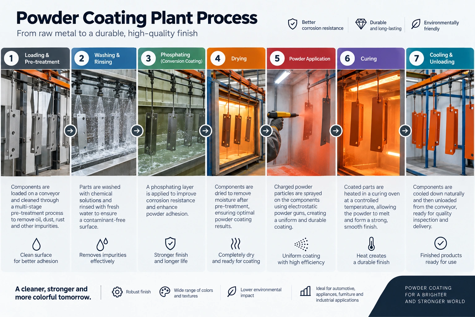
At its simplest, the process looks like this:
Incoming component → loading → pre-treatment → rinsing → drying → powder application → powder recovery → curing → cooling → inspection → unloading
The exact flow varies according to the substrate, component size, contamination level, production volume, coating specification and required corrosion performance.
The Powder Coating Institute describes powder coating as a dry finishing process in which electrostatically charged powder is attracted to a grounded part and subsequently cured with heat to form the finished coating.
For manufacturers evaluating a new line, however, understanding only the coating principle is not enough. The important question is how every stage of the plant works together.
Quick summary
| Stage | Main purpose | Typical equipment |
|---|---|---|
| 1. Loading | Position parts correctly for processing | Jig, hanger, trolley or conveyor |
| 2. Pre-treatment | Remove contamination and prepare the substrate | Dip tanks or spray tunnel |
| 3. Rinsing/final treatment | Remove residues and complete surface preparation | Rinse stages / conversion treatment |
| 4. Dry-off | Remove residual water | Dry-off oven |
| 5. Powder application | Deposit powder onto grounded parts | Spray booth and electrostatic guns |
| 6. Powder recovery | Capture and manage overspray | Cyclone/cartridge recovery system |
| 7. Curing | Melt, flow and cure the coating | Powder curing oven |
| 8. Cooling | Bring parts to safe handling temperature | Natural or forced cooling zone |
| 9. Inspection | Verify coating quality | Thickness, appearance and performance tests |
| 10. Unloading | Release finished components | Manual or automated unloading |
The major stages can also be grouped into the three fundamental operations identified by AMPP: pretreatment, coating and curing. A complete production plant adds material handling, drying, recovery, cooling, inspection and process controls around those core operations.
What is a powder coating plant?
A powder coating plant is an integrated industrial finishing system that prepares a component’s surface, applies electrostatically charged powder and cures the powder into a continuous protective or decorative coating.
Depending on production requirements, the plant may operate manually in batches or continuously using an overhead conveyor and automated equipment.
Brahma Fabricon supplies individual powder coating equipment as well as integrated plant systems; its equipment range includes pre-treatment, coating booths, curing ovens and associated systems. Explore powder coating equipment
Powder coating plant process flow: step by step
Step 1: Component inspection, loading and hanging
The process begins before the component enters the chemical treatment or spray booth.
Parts should first be checked for factors that can affect downstream processing, including:
- oil and machining fluids;
- rust or scale;
- weld spatter;
- sharp edges;
- masking requirements;
- drain holes and water traps;
- substrate type;
- part weight and dimensions.
Components are then placed on racks, jigs, trolleys or conveyor hangers.
Why hanging matters
Hanger design affects much more than material movement.
A poor hanging orientation can prevent pretreatment spray from reaching recessed surfaces, trap rinse water inside a component, create powder-shadow areas and interfere with electrical grounding.
In electrostatic application, grounding is particularly important because the charged powder must be attracted to the grounded workpiece.
Practical insight: hanger design should be considered part of the coating process, not simply part of material handling.
Step 2: Surface pre-treatment
Pre-treatment is the foundation of the coating system.
Its purpose is to remove substances that can interfere with coating adhesion and, when required, create an appropriate conversion layer on the metal.
Depending on the substrate and performance specification, the sequence can include:
Degreasing → rinsing → derusting/pickling where required → rinsing → conversion treatment → final rinse/passivation
The actual number of stages should not be selected simply because a plant is advertised as a “3-stage,” “7-tank” or “9-tank” system. The chemistry and sequence should match the component material, contamination and required coating performance.
For a more detailed explanation of dip, spray and chemical-treatment configurations, see Brahma Fabricon’s technical guide to pre-treatment systems for powder coating.
Dip vs spray pre-treatment
Dip pretreatment immerses components into treatment tanks. It can be useful for complex components where chemicals need access to recessed surfaces.
Spray pretreatment moves parts through an enclosed tunnel where pumps and nozzles apply the treatment solutions. It is commonly integrated into conveyorized production.
Brahma Fabricon also provides dedicated pre-treatment plant systems for different coating-line configurations.
Critical variables during pre-treatment
The exact parameters come from the chemical process being used, but operators may need to monitor:
| Parameter | Why it matters |
|---|---|
| Bath concentration | Determines whether the chemical stage performs as designed |
| pH | Helps control treatment chemistry |
| Temperature | Influences cleaning or conversion reaction |
| Dwell time | Determines exposure to each treatment |
| Spray pressure | Affects spray coverage in tunnel systems |
| Rinse quality | Helps prevent chemical carryover |
| Water quality | Can affect final surface condition |
| Nozzle condition | Blockage can create uneven treatment |
The chemistry supplier’s process specification should always take precedence over generic internet values.
Step 3: Rinsing and final surface conditioning
Rinsing is not simply “washing the chemicals off.”
Each rinse stage helps control contamination carried from one treatment stage into the next.
For example, excessive drag-out from a degreasing or conversion stage can contaminate the following rinse and gradually destabilize the process.
Depending on the coating specification, the final stages may also include a passivation, sealing or other approved conversion treatment.
What should leave this stage?
The part should be:
- chemically prepared;
- free from unacceptable treatment residues;
- suitable for the specified coating system;
- ready to be dried without being recontaminated.
The exact pretreatment must be matched to the substrate and service conditions rather than applied as a universal recipe.
Step 4: Dry-off
After wet pretreatment, the component must be adequately dried before powder application.
Residual water can interfere with powder deposition and can contribute to coating defects during heating.
A dry-off oven therefore sits between the pretreatment system and coating booth in many conveyorized lines.
The drying requirement depends on:
- component thickness;
- geometry;
- cavities and enclosed sections;
- retained water;
- conveyor speed;
- airflow;
- oven design.
Complex components may also require air blow-off before entering the dry-off oven.
A commonly overlooked issue
A component can appear dry externally while still holding water inside a channel, weld joint or recess.
Plant designers should therefore consider drainage orientation and water traps during the loading/hanger-design stage, not try to solve every moisture problem by increasing oven temperature.
Step 5: Electrostatic powder application
Once the part is clean and dry, it enters the powder coating booth.
Powder is delivered through one or more spray guns. In the most widely used electrostatic spray process, powder particles receive an electrical charge and are attracted to the grounded component. The Powder Coating Institute identifies electrostatic spray deposition as the typical application method for powder coating.
Depending on plant configuration, coating may be applied using:
Manual guns for lower volumes, frequent product changes or difficult areas.
Automatic guns and reciprocators for repeatable conveyorized production.
Automatic application plus manual touch-up where complex geometries require additional coverage.
Parameters that influence application
Coating quality can be affected by:
- gun position;
- part-to-gun distance;
- electrostatic settings;
- powder flow;
- atomizing/transport air;
- line speed;
- part geometry;
- grounding;
- powder condition;
- booth airflow.
More voltage or more powder is not automatically better.
Recesses, corners and complex geometries can behave differently from open flat surfaces, so recipes should be validated on actual production parts.
Step 6: Powder recovery and powder management
Not every particle sprayed from the gun deposits on the component.
Oversprayed powder is therefore captured by the booth’s recovery system. Depending on system design, this may involve cartridge filtration, cyclone separation or a combination of technologies.
A typical reclaim loop is:
Overspray → recovery system → separation/filtration → sieving or powder management → controlled return to powder feed
Recovery efficiency and transfer efficiency are not the same thing
This distinction is important when comparing plant specifications.
First-pass transfer efficiency describes how much powder reaches the part during the initial application.
Recovery efficiency describes how effectively suitable overspray is captured by the recovery system.
A plant can recover a high percentage of overspray while still having poor first-pass application efficiency.
For plant buyers, therefore, evaluating only a headline “powder recovery percentage” gives an incomplete picture.
Booth airflow, gun configuration, part presentation, powder management, color-change requirements and reclaim strategy should be evaluated together.
Step 7: Powder curing
After powder application, the coated component enters the powder curing oven.
Heat causes thermosetting powder to melt, flow and chemically crosslink into the final coating. PCI describes this heat-driven curing reaction as the stage that forms the coating’s cross-linked polymer structure.
Oven temperature is not the whole cure specification
One of the most important process-control principles is the distinction between:
oven air temperature
and
actual component or metal temperature.
Powders have defined cure schedules supplied by their manufacturer. Those schedules can vary substantially by formulation; Axalta, for example, publishes product-specific curing windows rather than one universal temperature/time value.
For this reason:
The correct curing condition should be based on the powder manufacturer’s technical data and verified against the actual temperature profile of the component.
A heavy steel fabrication heats differently from a thin sheet-metal enclosure even if both pass through the same oven.
What determines curing performance?
Key factors include:
- powder formulation;
- component material;
- component mass;
- section thickness;
- oven airflow;
- heat source;
- conveyor speed;
- oven length;
- actual part-metal temperature;
- time at the required cure temperature.
Undercuring can leave a coating without its intended final properties. Excessive exposure can also affect appearance or performance, depending on the powder formulation.
The conveyor is the backbone of a continuous powder coating line
In a conveyorized powder coating plant, the conveyor connects loading, pretreatment, drying, coating, curing and unloading into one production cycle.
This creates an important engineering relationship:
Conveyor speed affects both throughput and process dwell time.
Increasing line speed may increase theoretical production, but it can simultaneously reduce:
- pretreatment exposure time;
- dry-off time;
- powder application time;
- curing residence time.
OptiFinish’s process guide similarly identifies conveyor speed as a parameter that links process throughput with pretreatment and oven dwell requirements.
This is why line speed should not be changed purely to “produce more parts” without checking what that change does to the rest of the process.
Step 8: Cooling
The coating may have completed its oven cure, but the component is not necessarily ready for handling immediately.
Parts therefore move through a cooling section before unloading.
Cooling may use:
- ambient factory air;
- dedicated cooling zones;
- forced-air systems.
The required arrangement depends on production speed, component mass, available conveyor length and acceptable unloading temperature.
Adequate cooling also helps avoid damage caused by handling a coating before the component has reached a suitable temperature.
Step 9: Final quality inspection
A finished part should be verified against the customer’s coating specification rather than accepted only because “the finish looks good.”
Typical checks can include:
| Check | What it evaluates |
|---|---|
| Visual inspection | Color, coverage and surface defects |
| Film thickness | Whether coating build meets specification |
| Cross-cut test | Resistance of the coating to separation under the specified test method |
| Gloss | Surface gloss against agreed requirement |
| Color measurement | Consistency against approved standard |
| Cure verification | Whether the coating has reached required cure |
| Performance tests | Application-specific durability requirements |
For formal measurement procedures, ISO publishes ISO 2808:2019 for determining coating film thickness; ISO notes that the standard was reviewed and confirmed in 2026. ISO 2808:2019 — determination of film thickness
For cross-cut testing, ISO 2409:2020 specifies a procedure for assessing coating resistance to separation when a lattice pattern is cut through the coating. The appropriate test standard should ultimately be dictated by the customer’s specification or applicable quality plan. ISO 2409:2020 — cross-cut test
Step 10: Unloading, packing or transfer to assembly
Once the component has cooled and passed the required inspection, it can be:
- unloaded;
- packed;
- sent for assembly;
- transferred to another manufacturing operation;
- held for further quality verification.
Rejected parts should ideally enter a documented nonconformance and rework process rather than simply being recoated without identifying the underlying cause.
That matters because many apparent “powder problems” actually originate much earlier in the process.
Complete powder coating plant process flow diagram
A modern conveyorized plant can be represented as:
Incoming components
        ↓
Inspection / preparation
        ↓
Loading and hanging
        ↓
Pre-treatment
        ↓
Rinsing / conversion / final treatment
        ↓
Dry-off
        ↓
Powder coating booth
        ↓
Electrostatic powder application
        ↓
Powder curing oven
        ↓
Cooling
        ↓
Quality inspection
        ↓
Unloading / assembly / packingPowder feed
↓
Spray guns
↓
Workpiece + overspray
↓
Powder recovery
↓
Separation / sieving
↓
Controlled reclaim
↓
Powder feedAn original branded version of these two diagrams should be one of the main visual assets on the published page.
Batch vs conveyorized powder coating process flow
The fundamental coating stages remain similar, but material movement changes considerably.
| Factor | Batch plant | Conveyorized plant |
|---|---|---|
| Material movement | Manual trolley/rack | Continuous conveyor |
| Production | Intermittent | Continuous |
| Part flexibility | High | Depends on line design |
| Process timing | Controlled batch by batch | Linked to conveyor speed |
| Automation | Low to medium | Medium to high |
| Best suited for | Variable products, lower volumes, large parts | Repetitive medium/high-volume production |
| Expansion complexity | Usually simpler | Requires line/layout analysis |
| Process consistency | Operator-dependent | Potentially highly repeatable when controlled |
Manufacturers considering the continuous approach can also review Brahma Fabricon’s conveyorized powder coating plant selection guide.
How automation changes a modern powder coating plant
Modernization does not simply mean replacing manual spray guns with automatic ones.
Depending on line size and process requirements, automation can extend to:
Conveyor control — variable-speed drives and synchronized line movement.
PLC/HMI control — centralized monitoring of motors, burners, temperatures and alarms.
Recipe management — storing settings for different component families.
Automatic reciprocators — repeatable gun movement.
Powder management — controlled feeding, reclaim and color-change processes.
Temperature monitoring — tracking oven conditions and validating curing.
Interlocks and alarms — helping prevent operation outside defined conditions.
Utility monitoring — identifying abnormal energy, air or water consumption.
The useful question is not “How automated can the plant be?” but:
Which automation removes meaningful variation, labor, waste or production bottlenecks from this particular process?
Critical control points in the powder coating process
A strong plant design establishes measurable checks before defects reach final inspection.
| Process stage | Important control point | Possible consequence if uncontrolled |
|---|---|---|
| Loading | Orientation and grounding contact | Uneven coating or water trapping |
| Pretreatment | Chemistry and dwell time | Weak surface preparation |
| Rinsing | Water/rinse condition | Chemical carryover or deposits |
| Dry-off | Complete moisture removal | Pinholes or coating defects |
| Application | Grounding and application parameters | Poor coverage or excessive overspray |
| Recovery | Powder condition and contamination | Surface defects or inconsistent color |
| Curing | Actual part temperature/time | Under- or over-cure |
| Cooling | Handling temperature | Finish damage |
| Inspection | Defined acceptance criteria | Defects reaching assembly/customer |
Common powder coating defects and where to investigate first
When a coated component fails inspection, troubleshooting should follow the process backwards instead of immediately adjusting the spray gun.
| Problem | First areas to investigate |
|---|---|
| Poor adhesion | Surface cleanliness, pretreatment, conversion stage, cure |
| Pinholes/blisters | Moisture, dry-off, substrate outgassing, contamination |
| Thin recessed areas | Grounding, electrostatic settings, gun angle, geometry |
| Excessive powder consumption | Gun settings, part presentation, booth airflow, recovery |
| Orange peel | Film build, powder condition and cure profile |
| Color contamination | Booth cleaning, recovery circuit, powder handling |
| Incomplete cure | Part-metal temperature, dwell time, conveyor speed |
| Uneven film build | Grounding, gun positioning, part spacing, powder flow |
This stage-based troubleshooting model is more useful than treating every defect as an application-booth problem.
How to design the process flow for a new powder coating plant
A reliable process flow should be engineered backwards from the component and production requirement.
1. Define the workpiece envelope
Document maximum and minimum:
- length;
- width;
- height;
- weight;
- hanging orientation.
2. Identify substrate materials
Steel, galvanized steel, aluminium and other substrates may require different surface preparation and coating systems.
3. Define required coating performance
Determine the actual customer, OEM or environmental specification the finish must meet.
4. Determine production requirement
Calculate required parts per hour, shift or day and account for component spacing.
5. Select the pretreatment process
Choose chemistry, stage sequence and dip or spray configuration according to the substrate and performance requirements.
6. Engineer application and recovery
Consider part geometry, number of colors, color-change frequency, powder consumption and required automation.
7. Calculate curing requirements
Use the selected powder’s cure schedule plus actual component thermal load to determine oven and conveyor requirements.
8. Design material flow and plant layout
Loading, pretreatment, ovens, booth, cooling and unloading should form a practical flow without unnecessary handling or contamination risks.
9. Define process control and QC
Decide which variables must be measured, recorded and alarmed before equipment is ordered.
For manufacturers planning an entire facility rather than one machine, Brahma Fabricon’s turnkey powder coating plant setup guide covers the wider planning and installation process.
Practical engineering insights for plant buyers
Do not design the plant around the spray booth alone
The booth is visually prominent, but final finish performance depends on the complete sequence.
A sophisticated spray system cannot correct inadequate surface preparation or an incorrect cure.
Design around the actual product mix
A plant advertised with a certain “capacity” is not automatically capable of achieving that output for every component.
Part size, spacing, weight and thermal mass change the effective production capacity.
Treat line speed as a process parameter
Conveyor speed changes more than output. It changes the time available for multiple stages of the process.
Cure the coating according to the powder—not a generic temperature
The powder manufacturer’s technical data should define the required cure window. Published powder data demonstrate that curing schedules vary between formulations.
Measure causes, not just finished defects
Final inspection tells you that something failed.
Process monitoring helps tell you why it failed.
A well-designed plant therefore combines equipment with measurable operating parameters.
What determines the final powder coating plant configuration?
There is no single “best” process flow for every factory.
The configuration should be based on:
Product: dimensions, geometry, weight and substrate.
Volume: required throughput and shift pattern.
Finish specification: appearance, thickness, corrosion performance and customer requirements.
Pretreatment: contamination and conversion-treatment requirements.
Powder: chemistry, cure window and colors.
Color changes: number and frequency.
Utilities: electricity, fuel, compressed air, water and wastewater arrangements.
Factory: available floor area, height and material flow.
Automation: required labor level, traceability and process consistency.
Future capacity: realistic expansion requirements.
Brahma Fabricon’s broader powder coating plant range provides examples of how these systems can be integrated into complete plants.
FAQ
What is the correct process flow of a powder coating plant?
A typical flow is loading → pretreatment → rinsing → drying → electrostatic powder application → curing → cooling → inspection → unloading. Conveyorized plants integrate these operations into a continuous line.
What are the main stages of powder coating?
At the highest level, the three fundamental stages are pretreatment, powder application and curing. Industrial plants add material handling, rinsing, drying, recovery, cooling and quality control around these stages.
Why is pretreatment important before powder coating?
Pretreatment removes contamination and prepares the substrate for the specified coating system. Poor surface preparation can result in problems such as inadequate adhesion or premature coating failure.
What happens inside a powder coating booth?
Electrostatically charged powder is sprayed toward a grounded workpiece. Powder deposited on the part forms the uncured coating layer, while overspray is captured by the booth’s extraction and recovery system.
What temperature is required for powder coating?
There is no universal curing temperature suitable for every powder. The correct cure schedule depends on the specific powder formulation and should be taken from the powder manufacturer’s technical data, with attention to actual component temperature rather than relying only on oven-air temperature.
What is the role of the curing oven?
The curing oven supplies the heat required for the applied powder to melt, flow and, for thermosetting powders, chemically crosslink into the final coating.
What is the difference between a batch and conveyorized powder coating plant?
A batch plant moves groups of components manually between process stages, while a conveyorized plant continuously carries components through the line at controlled speed. Conveyorized systems are typically better suited to repeatable medium- and high-volume production.
What controls production capacity in a conveyorized powder coating plant?
Capacity depends on factors such as part dimensions, hanging pitch, conveyor speed, pretreatment dwell time, application requirements and curing requirements. Increasing conveyor speed alone does not necessarily increase usable output if another process stage becomes the bottleneck.
Conclusion
The powder coating plant process flow is best understood as one interconnected manufacturing system rather than a collection of booths, tanks and ovens.
A reliable line moves the component through:
loading → pretreatment → drying → powder application → curing → cooling → inspection → unloading
But the quality of the finished coating depends on how well those stages are matched.
Pretreatment must suit the substrate. Parts must be adequately dried. Application needs stable grounding and controlled powder delivery. The curing process must satisfy the powder’s specified cure window. Conveyor speed must support the required dwell times. Quality checks should verify the process rather than relying solely on appearance.
For manufacturers planning a new plant or upgrading an existing line, Brahma Fabricon can evaluate the component size, production requirement, plant layout, pretreatment, coating system, curing requirement and automation level before recommending a configuration. Start with the company’s powder coating plant solutions or review the complete turnkey plant setup guide before specifying individual equipment.